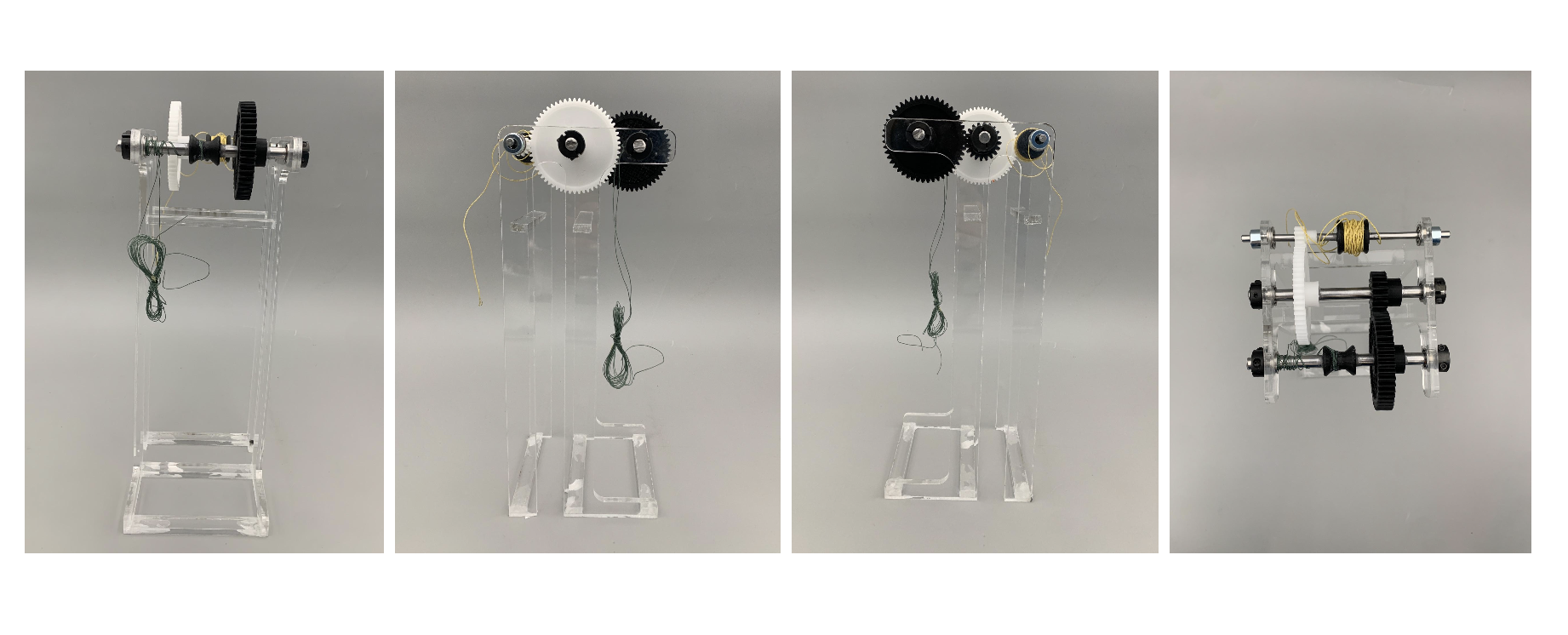
Mass-Optimized Lever-Lifting Transmission
Challenge
- Design a lightweight, efficient transmission to lift a 10kg weight on a lever by 10 cm using a maximum vertical mass drop of 2m.
- Minimize system mass and mass drop while maintaining structural integrity and mechanical efficiency
Action
- Transmission Design: Developed a two-stage gear system with two capstans to optimize force output and lever-lifting distance
- Performed inverse analysis and free body diagram calculations to determine gear ratios, torque requirements, and capstan radii
- Selected acetal gears for first stage and PLA 3D-printed gears for the second stage due to strength, mass efficiency, and manufacturability
- Implemented MATLAB script to iterate face width, pitch, and gear teeth for optimized gear strength and torque output
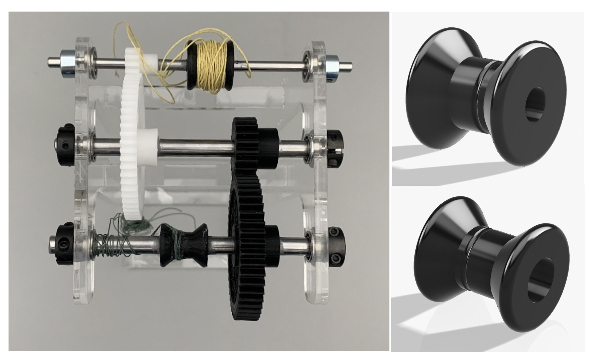
Gear layout showing two-stage transmission and capstan arrangement
- Capstan Design: Two PLA capstans with optimized radii (0.258’’ input, 0.163’’ output) to maintain 19:1 total transmission ratio
- Tapered geometry guides string toward the middle to reduce slipping and tension loss
- Validated using FEA, ensuring sufficient factor of safety under lever-lifting loads (up to 200 N)
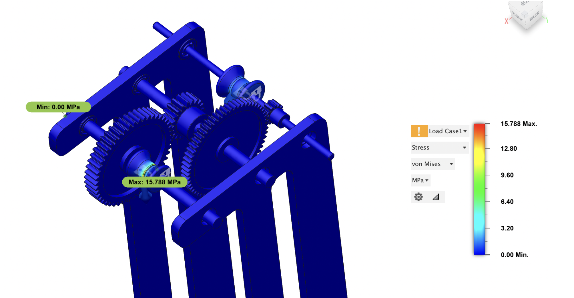
FEA of output capstan under lever-lifting load
- Acrylic Support Structure: Mass-optimized 30 cm high laser-cut acrylic frame
- Designed extended bottom leg and horizontal support beams to prevent tipping and bending
- Central vertical beam in compression, right vertical beam in tension; fillets increased to reduce stress concentration
- FEA confirmed stress distribution and stability under applied loads
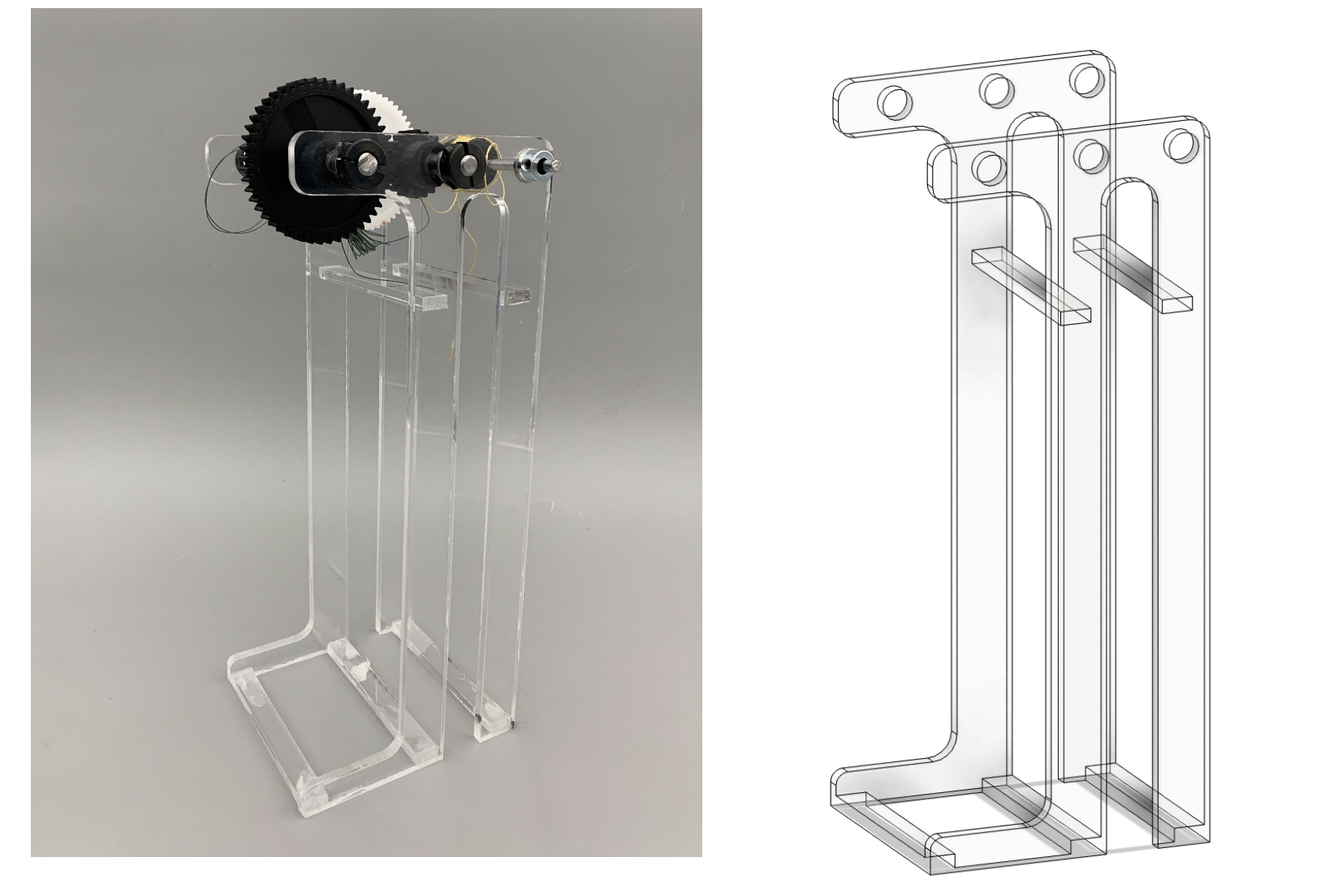
Laser-cut acrylic support structure with horizontal and vertical stabilizing beams
- Component Selection:
- Shafts: 12L14 carbon steel, 3/16’’ and 5/16’’ diameters for strength and cost efficiency
- Bearings: Stainless steel flanged ball bearings, selected for dynamic load capacity and smooth rotation
- Kevlar Strings: Matched breaking strength to input/output loads, achieving safety factors of 2.9 (output) and 18 (input)
- Shaft collars to prevent axial movement and account for non-orthogonal loads
Result
- Built a functional lever-lifting transmission system with a 19:1 total gear ratio, achieving 10 cm lift with 2 kg mass drop
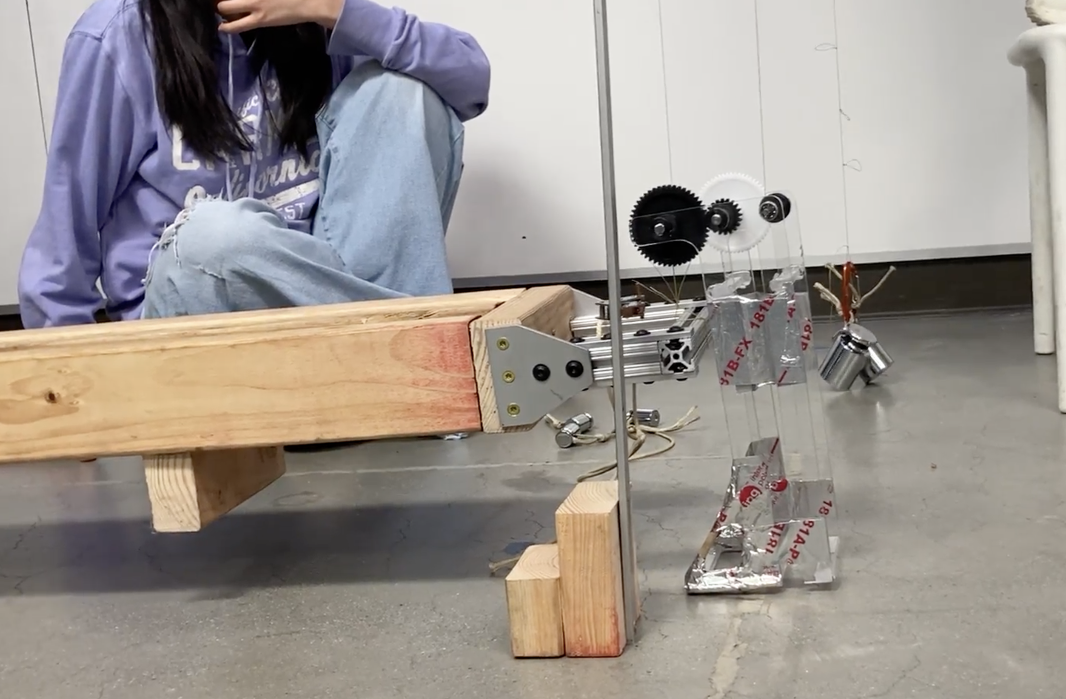
10 cm lever lift through the transmission system
- Validated structural integrity and mechanical efficiency through FEA, component analysis, and experimental testing
- Optimized mass, cost, and complexity by using two-stage transmission and lightweight materials
- One of four out of fifteen teams to achieve the required lift height